Table 1. Experimental Conditions
In this research work, an attempt has been made to investigate the effect of liquid nitrogen when it was applied to heat generation zones through holes made in the cutting tool insert during the turning of Aluminium 6061 – T6 alloy with uncoated carbide tool. The cryogenic result of the cutting temperature, cutting force, surface roughness, tool wear and chip form for the modified cutting tool insert have been compared with wet machining. The cutting temperature was reduced by 60 – 74% in cryogenic cooling over wet machining. The cutting force was decreased by 21 – 39% in cryogenic cooling with modified cutting tool insert over wet machining. It was also observed that in the cryogenic cooling method, the surface roughness was reduced to a maximum of 43% and the flank wear was reduced by 38 – 49% over wet machining. Cryogenic cooling enabled a substantial reduction in the geometry of tool wear through the control of tool wear mechanisms. The application of cryogenic cooling was considered to be more effective in chip breaking over wet machining.
Chip form and cutting tool wear are two important aspects commonly considered in evaluating the performance of a machining process. The machining of ductile materials in automated machines is more complicated because of the continuous chip. The cutting temperature is a decisive factor for other machinability indices such as the cutting force, surface finish and tool wear. In machining industries, a cutting fluid is used to cool and lubricate the cutting process, thereby improving tool life through reduction in tool wear. Conventional cutting fluids failed to provide the desired control of cutting temperature. Conventional cutting fluids are environmental contaminants and the government has imposed strict regulations limiting the dumping of cutting fluid waste (Shane Y. Hong, 2001). Cryogenic cooling is an environment- friendly clean technology for the desired control of cutting temperature, chip breaking and enhancement of tool life.
Wang et al. ( Wang et al., 1996; Wang & Rajurkar, 2000) have carried out an experimental investigation into the cryogenic machining of hard-to-cut materials. The results indicated a reduction in the cutting tool temperature and tool wear under cryogenic cooling, over dry machining. It was also reported that there was an improvement in tool life and surface finish under cryogenic cooling over dry machining. The favorable role of cryogenic cooling in chip breaking and reducing cutting temperature in turning was reported by Ding and Hong (Ding & Hong, 1996). Hong et al. (Hong and Ding, 2001; Hong et al., 2001) studied the influence of various cryogenic cooling approaches in the turning of Ti-6Al-4V alloy. A small amount of liquid nitrogen applied locally to the cutting edge is superior to emulsion cutting, in lowering the cutting temperature.
The influences of cryogenic cooling on tool wear, surface roughness and dimensional deviation in the turning of different steels have been studied (Dhar et al., 2002a; Dhar et al., 2002b). A substantial benefit of cryogenic cooling on tool wear, surface roughness and dimensional deviation through reduction in the cutting zone temperature, was reported. Dhar & Kamruzzaman (Dhar & Kamruzzaman, 2007) studied the effect of cryogenic cooling in the turning of AISI-4037 steel. The experimental results indicated the benefit of cryogenic cooling, mainly by substantially reducing the cutting temperature.
The tool wear and tool life of carbide inserts in the turning of Ti-6Al-4V alloy have been studied by Venugopal et al. (Venugopal et al., 2007a; Venugopal et al.,2007b). A reduced flank and crater wear in cryogenic machining over dry and wet machining was found. The favorable role of cryogenic cooling with modified tool holder on surface roughness, tool wear and tool life in turning have recently had been reported (Mirghani et al., 2007; Khan and Ahmed, 2008). Kalyan kumar and Choudhry (Kalyan kumar and Choudhry, 2008) worked on the cryogenic machining of stainless steel. It was observed that there was less cutting force in cryogenic machining over dry cutting.
Many researchers have carried out the experimental investigation of cryogenic cooling by liquid nitrogen in the machining of steels and titanium alloys. Currently, cryogenic cooling is carried out without modifying the cutting tool insert in the machining process. So the cutting tool insert was modified by Electric Discharge Machining (EDM) for supplying liquid nitrogen in the heat generation zones. The main objective of the present work is to experimentally investigate the influence of cryogenic cooling by liquid nitrogen through holes made in the cutting tool insert and its effect in the turning of Aluminium 6061 – T6 alloy.
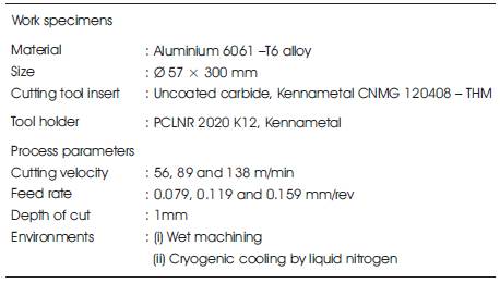
The turning experiments were carried out on Aluminium 6061 – T6 alloy bar of 57mm diameter by uncoated carbide insert under wet and cryogenic cutting conditions. The experimental details are given in Table 1. In wet machining, a cutting fluid was applied on the machining zone by using a nozzle. The emulsion cutting fluid was obtained by mixing the concentrate with water at a ratio of 1: 20 soluble oil. Figure 1 shows the cryogenic cooling setup. The experimental set up is shown in Figure 2.
Figure 3 shows the modified insert used for cryogenic cooling. A standard cutting tool insert CNMG 120408 – THM (ISO specification) was modified by Electric Discharge Machining for the cryogenic cooling requirements. A hole of dimensions of Ø 2 mm × 2.5 mm was made at the rake surface of the cutting tool insert. The rake surface hole is connected with the main and auxiliary flank surface holes (Ø 1 mm × 2 mm). The liquid nitrogen was directly applied to the hole made in the rake surface of the cutting tool insert, so that a major portion of liquid nitrogen can be splashed on to the chip-tool interface. A small amount of liquid nitrogen will reach the major and minor cutting edges of the cutting tool insert with the help of the two side holes. The evaporated gas from the main flank surface hole is directed away from the workpiece so that the possibility of excessive cooling is avoided.
The temperature was measured using a non-contact Infrared Thermometer with an accuracy of ±1.0% reading. The cutting force was measured by an online force measurement system including a Kistler type 9257B piezo-electric three component dynamometer, a kistler type 5070A12100 multi-channel charge amplifier and a PC-based data acquisition system (Dynaware). The surface roughness was measured using a contact type stylus - Surtronic 3+ Roughness Checker. In tool wear study, cutting inserts were examined under a scanning electron microscope (SEM).
Table 1. Experimental Conditions
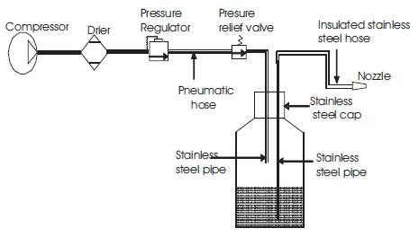
Figure 1. Schematic Diagram Of Cryogenic Cooling Setup
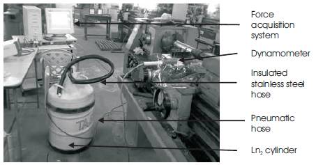
Figure 2. Experimental Setup
Figure 3. Schematic Representation of Cryogenic Cooling Method
The present work involving the turning of Aluminium 6061 – T6 alloy bar was carried out under wet and cryogenic cutting conditions. The cryogenic results of the cutting temperature, cutting force, surface roughness, tool wear and chip form for the modified cutting tool insert have been compared with those of wet machining.
Figure 4 shows the reduction in the cutting temperature due to cryogenic cooling over wet machining. The cutting temperature increased with an increase in the cutting velocity and feed rate. The cutting temperature at a cutting velocity of 138 m/min and feed rate of 0.159 mm/rev was 159°C and 63°C for wet machining and cryogenic cooling respectively. It was observed that the reduction in the cutting temperature due to cryogenic cooling was 60.38% over wet machining. This is because liquid nitrogen was supplied through holes made in the cutting tool so that the liquid nitrogen can be directly reach the sources of heat generation, which results in reduced cutting temperature at the cutting zone. The cryogenic cooling using liquid nitrogen enabled the reduction in the cutting temperature by 60 - 74% over wet machining. The reduction in the cutting temperature has significant influence on the cutting force, surface roughness and tool wear.
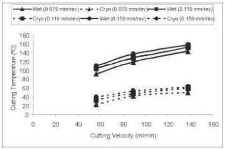
Figure 4. Variation in Cutting Temperature
When the cutting velocity (56 m/min) was increased to 89 and 138 m/min under the constant feed rate of 0.119 mm/rev, the variation of percentage reduction in cutting temperature due to cryogenic cooling was found to be 5.78% and 7.79% respectively. This result indicates that with an increase in the cutting velocity, the cryogenic cooling effect is decreased. When the feed rate (0.079 mm/rev) was raised to 0.119 and 0.159 mm/rev under the constant cutting velocity of 138 m/min, the deviation of percentage reduction in the cutting temperature due to cryogenic cooling was observed to be 3.8% and 4.2% respectively. The result shows that with an increase in the feed rate, the cryogenic cooling effect is decreased. Based on the experimental results, the cryogenic cooling effect decreased with an increase in the cutting parameters. This is because the cutting temperature increased with an increase in the cutting parameters, thereby changing the chip-tool contact nature.
Figure 5 shows the comparison of the cutting force under wet and cryogenic environments. The cutting force decreased with an increase in the cutting speed due to a decrease in the shearing area and also the cutting force increased with an increase in the feed rate due to the increase in chip load. The cutting force at a cutting velocity of 89 m/min and feed rate of 0.159 mm/rev was 158 N and 115 N for wet machining and cryogenic cooling respectively. It was observed that a reduction in the cutting force due to cryogenic cooling was 27.22% over wet machining. This is because the application of liquid nitrogen reduced the friction at the chip-tool interface due to the formation of a fluid cushion. It was observed from Figure. 5, that the cutting force was reduced in cryogenic cooling over wet machining. The reasons for the decreased cutting force in cryogenic cooling were that the lower cutting temperature at the cutting zone, reducing the friction at the chip-tool and work-tool interactions, reducing the tool wear and maintaining the strength and hardness of tool material. The cryogenic cooling decreased the cutting force by 21 – 39% over wet machining. The cutting forces decreases under cryogenic cooling for all the speed-feed combinations as reported in an earlier work [1] (Dhananchezian and Pradeep Kumar, 2011, [1] Dhananche zian et al., 2011).
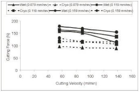
Figure 5. Comparison of cutting force
The variation in surface roughness with different cutting velocities under wet and cryogenic cutting conditions is shown in Figure 6. The surface roughness decreased with an increase in cutting velocity and it increased with an increase in the feed rate. The value of surface roughness at a cutting speed of 56 m/min and feed rate of 0.159 mm/rev was 1.78 µm and 1.02 µm for wet machining and cryogenic cooling respectively. The reduction in the surface roughness over wet machining was observed to be 42.7% for cryogenic cooling. In cryogenic cooling, liquid nitrogen was applied to the rake and flank surfaces of the tool simultaneously, which results in reducing the friction between the newly generated workpiece surface and the tool flank surface, in controlling the cutting temperature and reducing the geometry of tool wear, thereby decreasing the surface roughness. The cryogenic cooling reduced the surface roughness by 34 – 43% over wet machining. The value of surface roughness decreases under cryogenic cooling by liquid nitrogen as reported in an earlier work [1] (Dhananchezian and Pradeep Kumar, 2011, [1] Dhananchezian et al., 2011).
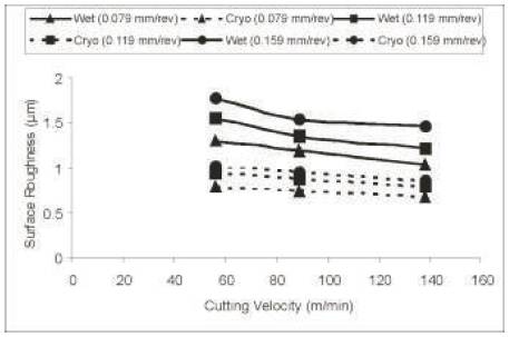
Figure 6.Variation in surface roughness with cutting velocity
The reduction in flank wear due to cryogenic cooling over wet machining for a constant feed rate of 0.159 mm/rev is shown in Figure 7. The flank wear increased with an increase in the cutting velocity. The flank wear at a cutting velocity of 56 m/min and feed rate of 0.159 mm/rev was 391 µm and 241 µm, for wet machining and cryogenic cooling respectively. It was observed that the reduction in flank wear due to cryogenic cooling was 38.36% over wet machining. This is due to the control of tool wear mechanisms by the application of liquid nitrogen in the heat generation zones, which results in decreased geometry tool wear. The influence of cryogenic cooling using liquid nitrogen reduced the flank wear by 38 – 49% over wet machining. The tool wear was consistently reduced in cryogenic cooling as reported in an earlier work [1] (Dhananchezian and Pradeep Kumar, 2011, [1] Dhananchezian et al., 2011).
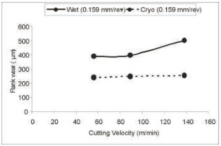
Figure 7. Comparison of flank wear under wet and cryogenic machining
The SEM view of worn tools after 5 minutes of machining under wet and cryogenic environments for the feed rate of 0.159 mm/rev is shown in Figure 8. The rake and flank wear increased with an increase in the cutting velocity. In cryogenic cooling, less abrasion and attrition wear was observed at the flank surface and also less crater wear was observed on the tool rake surface due to a reduction in the cutting temperature. In wet machining, high flaking was observed at the tool rake surface due to strong adhesion between the chip and the rake surface. It was also observed that the nose of the tool underwent substantial wear in wet machining. Cryogenic cooling by liquid nitrogen reduced the geometry of tool wear through a reduction in temperature-dependent tool wear mechanisms through the control of the cutting temperature at the machining zone. The tool wear was substantially reduced in cryogenic cooling as compared to wet machining. The main reason is that, the liquid nitrogen applied directly to the sources of heat generation that cools the cutting edge effectively and reduces the coefficient of friction at the chip-tool and work-tool interfaces.
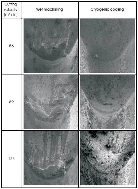
Figure 8. SEM views of the used tools after 5 min of machining under wet and cryogenic cooling
The collected chip samples during the turning of Aluminium 6061 – T6 alloy at the feed rate of 0.159 mm/rev under wet and cryogenic machining are shown in Figure 9. In wet machining, the chips are composed of arcs linked together in a continuous form. It was evident that a change in the cutting velocity produces no clear difference in the chip breaking. Short chips were obtained in cryogenic cooling. This is because when liquid nitrogen was supplied to the rake and flank surfaces of the cutting tool insert, some amount of liquid nitrogen splashed on the chip surface. So the nature of the chip material changes from ductile to brittle. This provides the possibility of improving chip breaking by cryogenic cooling.
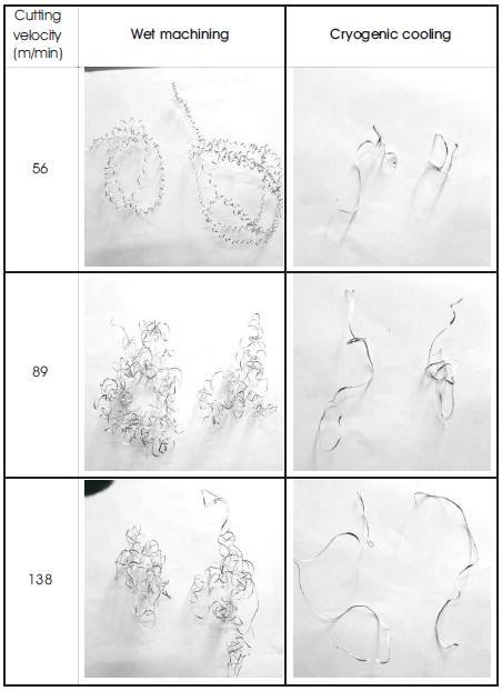
Figure 9. Effect of Cryogenic Cooling on Chip Breaking
In cryogenic cooling, the cutting insert was modified for the efficient use of liquid nitrogen in the turning operation. The experiments on the turning of Aluminum 6061 – T6 alloy were carried out under wet and cryogenic environments. Cryogenic cooling using liquid nitrogen reduced the cutting temperature by 60 – 74% over wet machining. Cryogenic cooling provided the benefits mainly by substantially reducing the cutting temperature. Cryogenic machining decreased the cutting force to 21 - 39% over wet machining. Cryogenic cooling by liquid nitrogen reduced the flank wear to 38 – 49% and decreased the surface roughness by 34 - 43% over wet machining. Cryogenic cooling using liquid nitrogen provided short chips in the turning of Aluminium 6061 – T6 alloy. Experimental investigations proved that cryogenic cooling with a modified cutting tool insert have shown better results on the cutting temperature, cutting force, surface roughness, chip form and tool wear over wet machining.